
Layering solves different failure modes
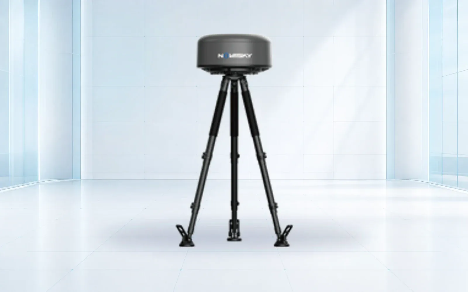
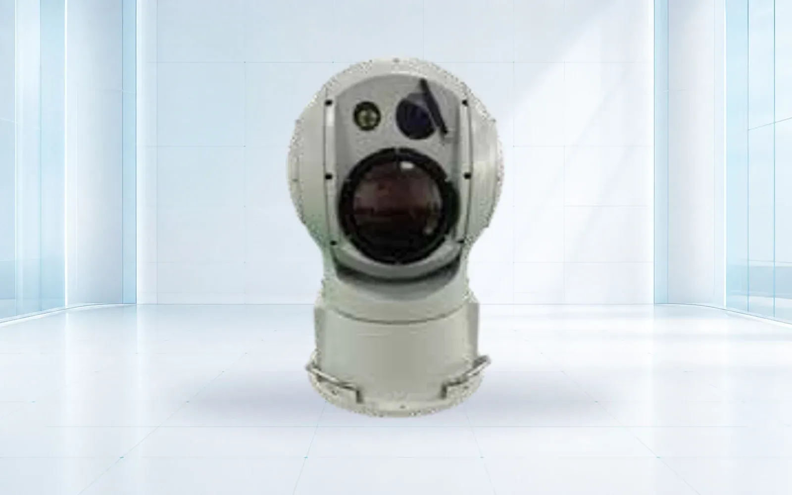
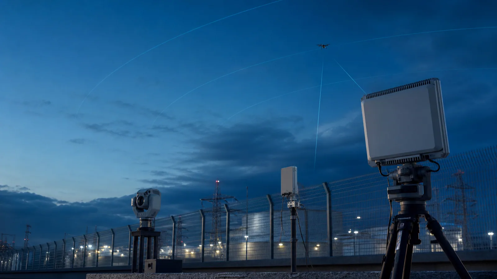
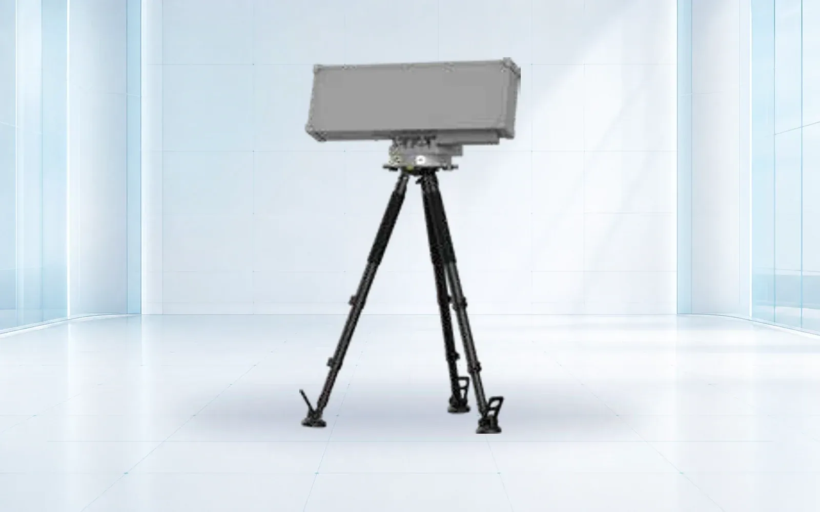
Radar can provide range, bearing and motion without depending on the target’s control link. RF detection can add protocol or controller clues when emissions are present. Electro-optical sensors provide visual evidence but depend on line of sight, atmosphere, target size and cue quality. None of these strengths cancels the others’ limitations.
A sensible counter-UAS system uses one sensor to cue or corroborate another. The design objective is not the longest isolated detection. It is a stable, explainable chain from initial observation to operator decision.
| Layer | Useful contribution | Important limitation |
|---|---|---|
| Radar | Range, bearing and motion without target emissions | Clutter and target profile affect detection |
| RF sensing | Protocol and controller clues when links transmit | Autonomous or unfamiliar links may be silent |
| Electro-optical | Visual confirmation and evidentiary imagery | Weather, light and cue accuracy affect acquisition |
| Command platform | Correlation, zones, workflow and records | Poor event semantics can create operator overload |
| Active response | May interrupt or redirect a target | Authority, spectrum and safety constraints are decisive |
Define the test target, clutter and protected volume
A range figure without a target definition is almost meaningless. Small multirotors, fixed-wing aircraft, autonomous routes and low-speed hovering present different radar and RF signatures. Trees, cranes, birds, vehicles, water and nearby transmitters create site-specific clutter.
Acceptance testing should include representative approaches, altitudes, speeds and backgrounds. It should also run long enough without a target to expose nuisance alarms. A system that finds the test drone but overwhelms operators during normal activity has not passed an operational test.
Track probability of detection by target and approach, initiation delay, continuity, position error, cue handoff time, classification confidence and nuisance alarms per operating hour. Also test what happens when a sensor or network path is unavailable.
Response is a separate legal design
Jamming, spoofing and other active measures can interfere with communications and navigation beyond the intended target. Rules vary by country and by the authority of the end user. The project must establish spectrum permission, safety boundaries, command authority, logging and abort conditions before an active layer is considered.
A detection-only system can still create substantial value through early warning, evidence capture, airspace coordination, physical security response and law-enforcement escalation. Treating that as a valid architecture prevents a technically impressive but unusable purchase. The border security reference architecture and critical infrastructure protection architecture both preserve this separation.
The operator interface is part of detection performance
Operators need a concise incident picture: source confidence, track history, camera view, protected-zone context and the next permitted action. Alarm rules should reflect risk zones and target behavior rather than make every detection equally urgent.
Training should include nuisance-alarm review, loss of track, conflicting sensor reports and evidentiary export. A layered system succeeds when people can make timely, defensible decisions under real site conditions. Related engineering and compliance material is collected in the technical resource hub.
Design coverage by decision zone
A site plan should distinguish where the team wants early awareness, where it needs reliable tracking and where an incursion creates immediate consequence. Those zones rarely form neat circles around a sensor. Terrain, buildings, public roads, neighboring property, airspace routes and the locations from which operators can act all shape the useful protected volume.
For each zone, state the target classes, minimum track quality, required warning time and the decision the system must support. Early-warning coverage may tolerate lower classification confidence if it gives the operator time to cue another sensor. A critical zone may demand continuous track, visual confirmation and a faster notification path.
| Zone design input | Question to resolve | Test output |
|---|---|---|
| Target set | Which sizes, speeds, emissions and flight modes matter? | Representative target matrix |
| Approach geometry | Which altitude, bearing and background are credible? | Mapped routes and coverage result |
| Operational consequence | What changes when the target enters this zone? | Agreed alarm and escalation rule |
| Corroboration | Which second source should confirm the event? | Measured cue and handoff time |
| Degraded mode | What remains when a layer is unavailable? | Tested reduced-capability procedure |
Build one event record across the layers
Sensor integration is more than placing icons on the same map. Radar tracks, RF observations, camera cues and operator notes need stable identifiers, synchronized time and explicit confidence. Preserve the original observation as well as any fused classification; otherwise, an operator cannot later explain which source supported a decision.
The command platform should show sensor health and gaps alongside target information. It should also distinguish “not detected,” “not covered” and “sensor unavailable.” Those states have different operational meanings. Evidence export should include the timeline, track history, images or clips, alarm changes, acknowledgements and configuration relevant to the event.
Accept the system in phases
Begin with survey and coverage assumptions, then test each sensor independently before measuring cross-sensor cueing and the full operator workflow. Use a controlled target matrix and repeat important routes enough times to expose variability. Record weather, clutter, target configuration, sensor settings and operator staffing for every run.
The final phase should include non-target operating hours, network or sensor loss, conflicting observations and evidence export. Pass criteria should cover detection and continuity, but also nuisance-alarm rate, cue time, operator workload and recovery. This staged method identifies whether a failure belongs to geometry, a sensor, integration or procedure instead of hiding it inside one headline range figure.